Batch exporting flat patterns from the assembly and multi-body part
This module allows to batch automate the exporting of flat patterns from the components of the active assembly or the multi-body part.
All types of solid bodies are supported. Tool will find the best orientation and method of exporting the flat pattern. Refer Generating Flat Pattern for more information
User has an option to customize the output name of the files and optionally include the etching note into the flat pattern with the flexible value.
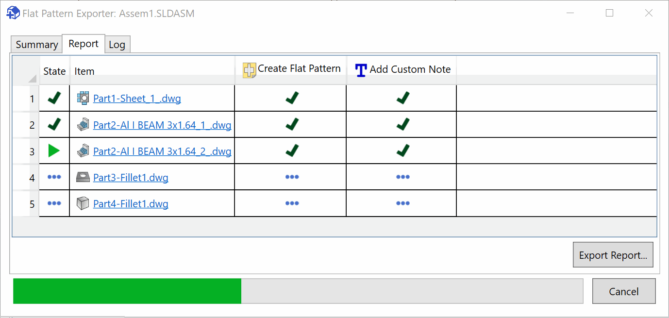
Output process is captured into the progress dialog. Different types of solid bodies are marked with the corresponding icon (e.g. sheet metal, weldment, flat plate or solid body).
User has an option to cancel the process.
Input Page
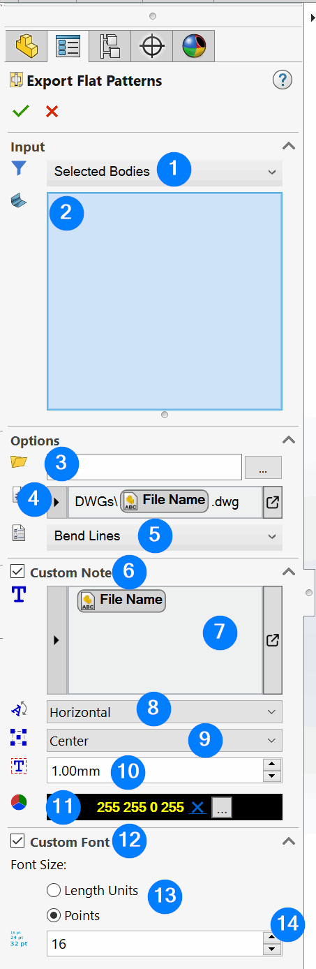
- Input filter
- Selected Bodies. Enables the selection box to select bodies or components from the active model manually
- Sheet Metal. Processes all sheet metal bodies in the part or assembly. Refer (Generating flat pattern of sheet metal bodies)[#sheet-metal]
- Weldment. Processes all structural member (weldment) bodies in the part or assembly. Refer (Generating flat pattern of weldment bodies)[#weldment]
- Flat Plate. Processes all flat plate bodies in the part or assembly. Refer (Generating flat pattern of flat plate bodies)[#flat-plate]
- Solid Bodies. Processes all solid bodies in the part or assembly. Refer (Generating flat pattern of solid bodies)[#solid-body]
- All Bodies. Processes all bodies in the part or assembly
- Selection box for selecting bodies or components to process if the filter is set to Selected Bodies
- Output folder for the flat pattern files. If empty files will be output into the same directory as input part or assembly. Relative or absolute path can be specified in this box
- Output naming template. Specify the extension of the output (e.g. .dxf, .dwg, .pdf etc.) Refer Expression Box Control for more information. Supported variables:
- File Name - name of the file without extension flat pattern is generated from
- Custom Property - value of the specified custom-property
- Cut-List Custom Property - value of the specified cut-list custom property
- Item Number - cut-list item number (used in the BOM and Cut-List tables)
- Quantity - quantity of the cut-list. This is the quantity of the cut-list body within the part multiplied by the total quantity of the part in the assembly
- Configuration - name of the referenced configuration of the body's component
- Cut-List/Body Name - name of the cut-list or body
- Output options for generating the flat pattern
- Geometry Only - only geometry is included into the output
- Bend Lines - includes bend lines into the flat pattern
- Bend Notes - adds bend notes into the flat pattern
- Sketches - includes visible sketches into the flat pattern
- Option to add custom note onto the flat pattern
- Value of the custom note. Supports the same variables as the Output Name Template box. Refer Smart TextBox Control for more information.
- Orientation of the custom note
- Horizontal - orient note horizontally
- Vertical - orient note vertically
- Auto - find the best orientation direction for the note based on the width and height of the flat pattern
- Dock location of the custom note
- Top Left - positions the note in the top left corner
- Bottom Left - positions the note in the bottom left corner
- Top Right - positions the note in the top right corner
- Bottom Right - positions the note in the bottom right corner
- Center - positions the note in the center
- Margins of the custom note
- Color of the custom note
- Option to assign the custom font size to the note
- Type of the font size
- Size of the font
Generating Flat Pattern
Tool will generate the output flat pattern differently based on the type of the geometry
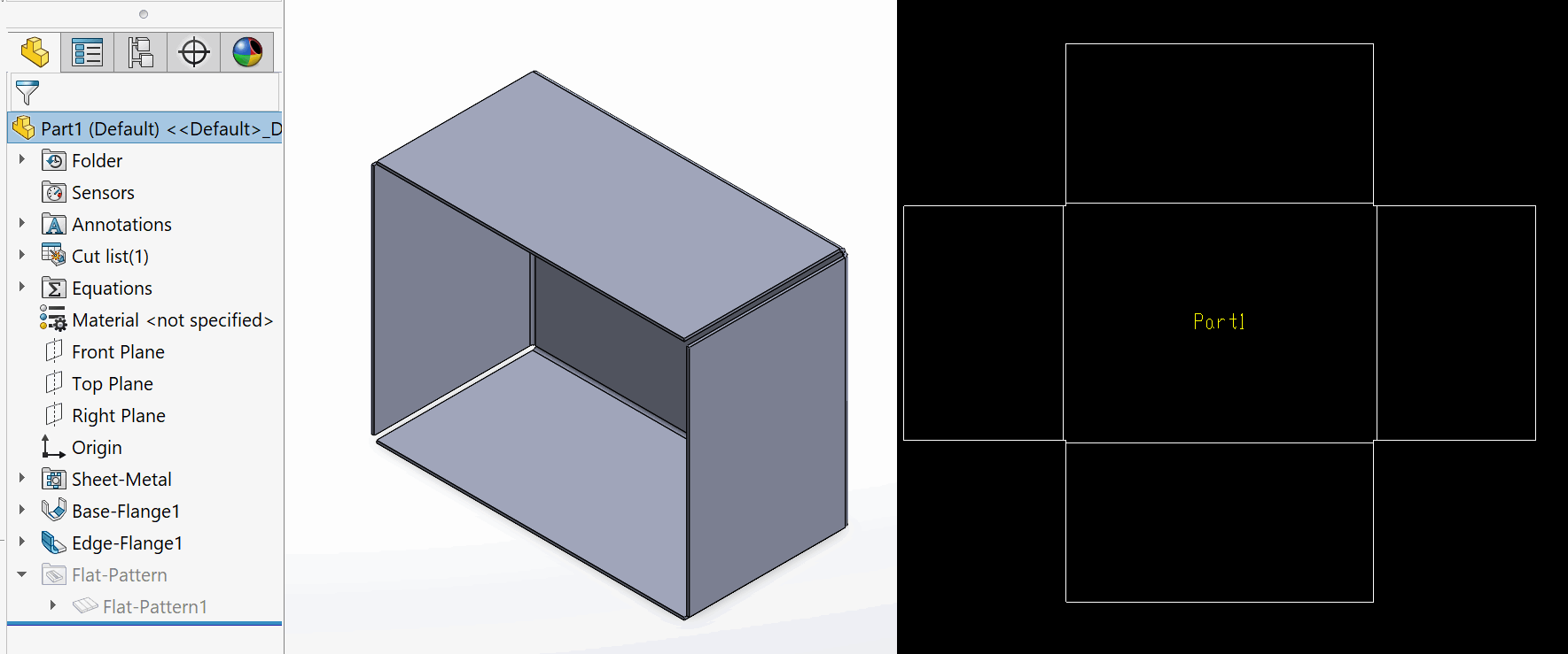
Sheet Metal
For the sheet metal bodies, tool will create a single flat pattern view and output to the specified format.
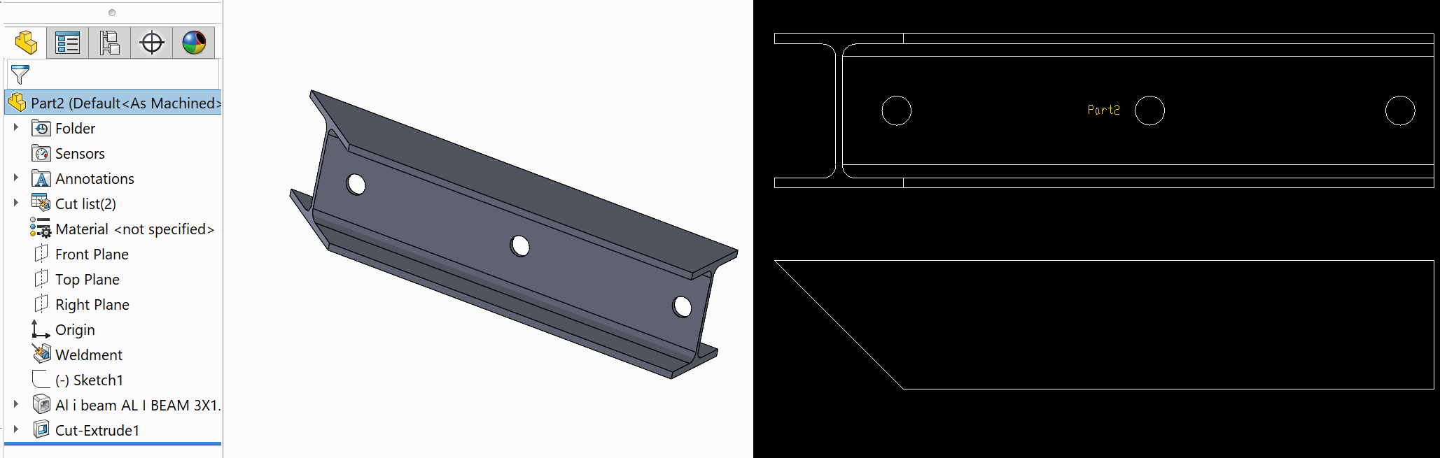
Weldment
For the structural member bodies (weldments) tool will create 2 views based on the orientation of the profile (top and side views)
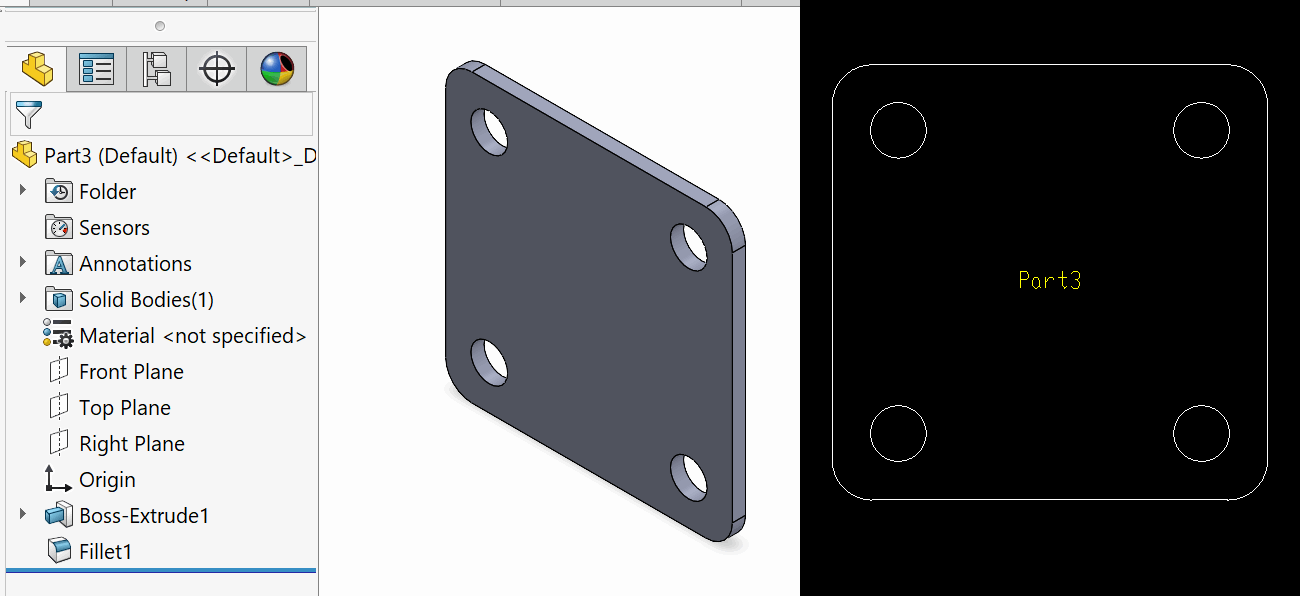
Flat Plate
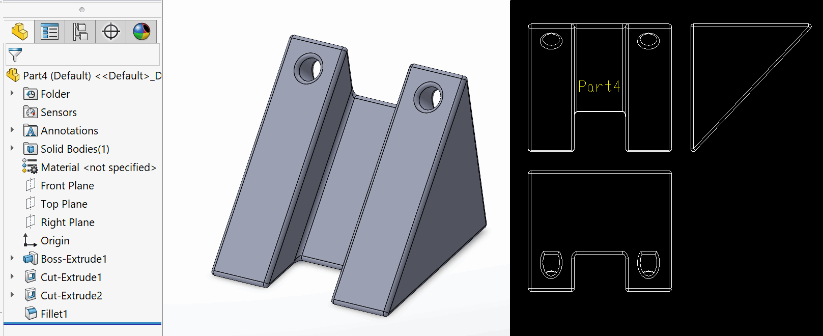
Flat plate is the solid body of a constant thickness. This body does not necessarily need to contain the sheet metal feature. Tool will find the largest planar face and calculate the orientation based on the best fit bounding box relative to the found face. Single view will be generated.
Solid Body
Any solid body which does not fall into any of the above categories will be considered as a solid body. 3 views will be created for this body based on the orientation of the best fit bounding box.